01COMPLEMENT THE SIGNALS
Listen beyond the dashboard.
Sound can reveal mechanical changes that may not appear as a diagnostic code. Pair it with vehicle context to support a more complete review.
ACOUSTIC + OBD CONTEXT↗
 FLEET INTELLIGENCE
AUTOSONIX × TCME
Acoustic intelligence can add a new mechanical signal to connected fleet workflows—helping turn vehicle sound into a more informed maintenance conversation.
THE OPPORTUNITY / 01
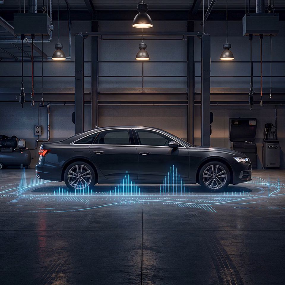
TCME’s Middle East priority is to reduce maintenance disruption in B2B fleets, starting with a selected gasoline sedan and limousine cohort. AutoSonix combines acoustic models, guided capture and synchronized vehicle context to make mechanical sound a measurable input to that fleet platform.
Sound can reveal mechanical changes that may not appear as a diagnostic code. Pair it with vehicle context to support a more complete review.
Use structured acoustic information to help prioritize a review, support a maintenance decision, or direct a vehicle for inspection.
Connect each reviewed signal to technician findings and repair outcomes. Agree the success measures together before expanding.
THE TECHNOLOGY / 02
A purpose-built capture workflow connects acoustic data with vehicle context and makes the result available for review—creating a practical starting point for future fleet integration.
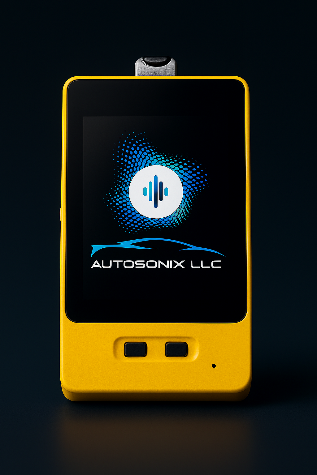
ListenLink captures engine-bay sound during a guided, temporary inspection and can move between vehicles.
The iOS / Android workflow pairs recordings with VIN and available OBD signals, including RPM, temperature and speed.
Purpose-built acoustic models screen for patterns of interest.
The Powertrain Index (PTX™) combines assessment signals to support review, alongside the portal and API for downstream workflows.
Current scope: guided capture and review. Fleet trend analysis, continuous monitoring and embedded in-vehicle sensing require further validation and co-development.
One ListenLink captures sound from the engine-bay area across multiple components. The current workflow uses a temporary acoustic sensor, an OBD adapter physically connected to the vehicle port, and a mobile app. Capture guidance keeps placement and operating conditions consistent.
CURRENT SOUND ANALYSIS / 03
AutoSonix looks for acoustic signatures associated with mechanical conditions. Today’s focus is gasoline passenger and light-duty vehicles, using guided capture to identify sound patterns that warrant review.
ACROSS MAKES & MODELS
AutoSonix learns recurring acoustic characteristics of mechanical anomalies across many gasoline makes and models. A valvetrain, timing-chain or bearing-noise signature is the target of recognition. The method does not require a separate “healthy vehicle” sound template for every make and model. Known-good examples are still used to validate performance and measure false alerts in the selected fleet.
A selected gasoline sedan and limousine cohort provides the initial focus. Choosing that cohort focuses the PoC on TCME’s operating needs and verifies performance in its vehicles. It does not define the boundaries of the underlying sound-recognition approach.
A mechanical sound pattern that can occur across different vehicles.
| Assessment area | Component / check | Patterns of interest |
|---|---|---|
| INTERNAL ENGINE | 01Valvetrain | Loud valvetrain or lifter noise and patterns associated with valve lash or excessive wear. |
| INTERNAL ENGINE | 02Timing chain | Timing-chain noise, including startup-related characteristics when the vehicle is equipped with a timing chain. |
| INTERNAL ENGINE | 03Lower engine | Rod-knock-type patterns, connecting-rod bearing and crankshaft bearing noise. This refers to mechanical lower-end noise, rather than combustion detonation. |
| EXTERNAL / ACCESSORIES | 04Accessories & belt drive | Accessory and bearing-noise patterns associated with idler pulleys, alternators, A/C compressors and mechanically driven power-steering pumps, where fitted. |
| EXTERNAL / EXHAUST | 05Exhaust | Abnormal exhaust rumble and leak characteristics, including muffler and exhaust-manifold examples. |
| GUIDED WORKFLOW CHECK | 06Transmission / static shift | Abnormal sounds observed during the guided static-shift check, such as grinding or whirring, contribute to the assessment. |
No abnormal sound observed is also an assessment outcome, considered alongside OBD and vehicle context.
The current engine-sound assessment groups results as no abnormal mechanical sound, abnormal external mechanical sound, or abnormal internal mechanical sound, with upper- and lower-engine distinctions. The table illustrates patterns of interest within these broader assessment categories, not six separate component-level model outputs. Component examples apply where fitted. Service inspection confirms the cause. The transmission row describes the guided static-shift check; a driving-based transmission model remains a development area.
ADAPTABLE TO THE USE CASE
The current models already recognize mechanical sound signatures across many gasoline makes and models, so adding a new sound of interest builds on that foundation rather than starting over. Using our existing acoustic-development tools, we can adapt the current model to the components, vehicles and operating conditions that matter to TCME, typically much faster than building a model from scratch. Each new profile still needs representative data and validation before deployment.
Suspension / shock noises · Rear-end / driveline noises · Diesel-specific signatures
These examples are a starting point. Additional acoustic profiles can be developed around other components, anomalies and operating needs relevant to your use case.
Additional profiles require representative data, model development and validation before deployment.Select the vehicle cohort, target sound and maintenance decision it should support.
Collect representative recordings with confirmed service findings and known-good examples.
Extend the model to recognize the relevant acoustic signature and account for operating conditions.
Measure detection and false alerts, then agree how the result enters the fleet workflow.
THE TCME CONNECTION / 04
The integration priority is acoustic data delivered into TCME’s backend for analysis and operational action. TCME’s available connected-vehicle data can add context to the AutoSonix signal.
Sound-profile classification, capture time and associated vehicle identity.
Available data communication module (DCM), telematics or OBD information, operating conditions and service history.
Agree data fields, identity matching and delivery frequency with TCME’s platform team.
Example fields and wording for discussion. The final payload, alert logic and operator actions are agreed during integration.
For fleets of thousands of vehicles, TCME’s goal is on-the-go alerts between service visits: identify the vehicle, flag the relevant acoustic change and direct the fleet team to act. Today’s portable scans establish the evidence. Continuous sensing and automatic fleet alerts are the co-development path.
IMPLEMENTATION & PARTNERSHIP
Integration and deployment considerations, ready for technical and management review.
The acoustic model analyzes sound as its own input. The current workflow also synchronizes it with live OBD parameters, DTCs and vehicle identity. A quiet DTC record can still accompany an acoustic review signal.
Missing OBD data is a different case: the current inspection process normally stops if it cannot obtain the VIN needed to link the recording to a vehicle. A TCME integration could use an agreed vehicle-identity and data source. Missing-data handling must be defined for that workflow.
API or webhook delivery is the proposed primary integration route. TCME can combine acoustic results with its own vehicle data and use them in its fleet-management experience. An SDK can support app integration where needed.
A TCME-branded workflow, a dedicated model and a TCME-operated deployment are options to scope jointly. Exclusivity requires a separate agreement defining the use case, territory, rights and commercial terms.
The current inspection service is hosted in the US. Regional hosting or a model operated within TCME’s environment can be evaluated, with architecture, data handling, support responsibilities and licensing agreed during technical scoping.
The stated operating range of −40°C to +65°C applies to the main chip and Wi-Fi module only. It is not a qualification of the complete ListenLink device or a permanent under-hood installation. The PoC should measure temperatures at the actual sensor location and confirm complete-device limits, exposure duration and operating margin.
ListenLink is temporarily placed for guided capture today. A permanent under-hood sensor requires a separate qualification plan for heat exposure, power, mounting and connectivity. UAE field qualification remains part of the validation plan.
The current inspection model combines a US$299 hardware package with usage-based pricing tailored to inspection volume and deployment requirements.
TCME’s fleet deployment needs a separate scoped proposal covering fleet volume and capture frequency, integration, hosting, custom model or hardware development, and support. A TCME-operated solution could use a licensing structure.
A PROOF OF CONCEPT / 05
Start with the capability available to test today: ListenLink, the mobile workflow, OBD context and acoustic assessment. A selected gasoline sedan and limousine cohort can establish evidence before vehicle-integrated hardware development.
Agree the gasoline sedan and limousine cohort and supported assessment categories. Confirm hybrid eligibility and capture procedures separately; scope new profiles as a development track.
Record vehicle identity, mileage, conditions and available operating context.
Match reviewed signals to inspection findings, repair orders or known-good checks.
Assess detection, alert burden, workflow fit and integration effort before expanding.
Capture and false-alert checks: account for normal injector ticking across direct-injection (DI) and port-fuel-injection (PFI) engines when validating valvetrain alerts. Hybrid vehicles need a confirmed capture procedure that accounts for engine stop/start behavior before inclusion in the PoC.
ANSWERING THE VALIDATION QUESTION
Review available labeled recordings and field evidence under NDA, including gaps in component-level confirmation. Then establish an agreed evidence set in TCME’s chosen cohort.
THE DEVELOPMENT HORIZON / 06
The future vision brings compact acoustic sensors, under-hood integration and an in-vehicle interface together. For TCME, the first priority is a validated path from today’s guided scans to connected fleet maintenance.
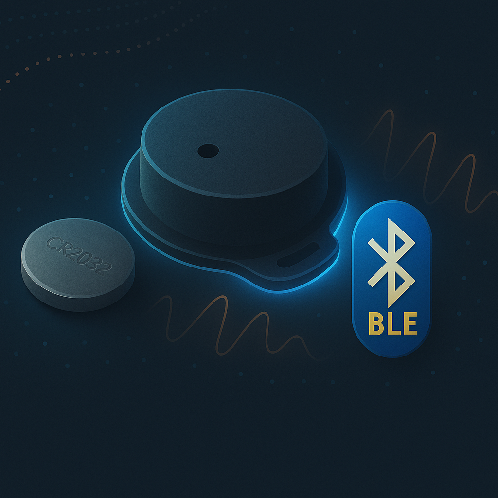
A small sensor concept for capturing the sound signatures relevant to the vehicle and use case.
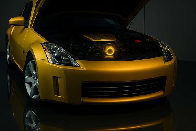
Explore embedded placement and edge processing to support monitoring between service visits.
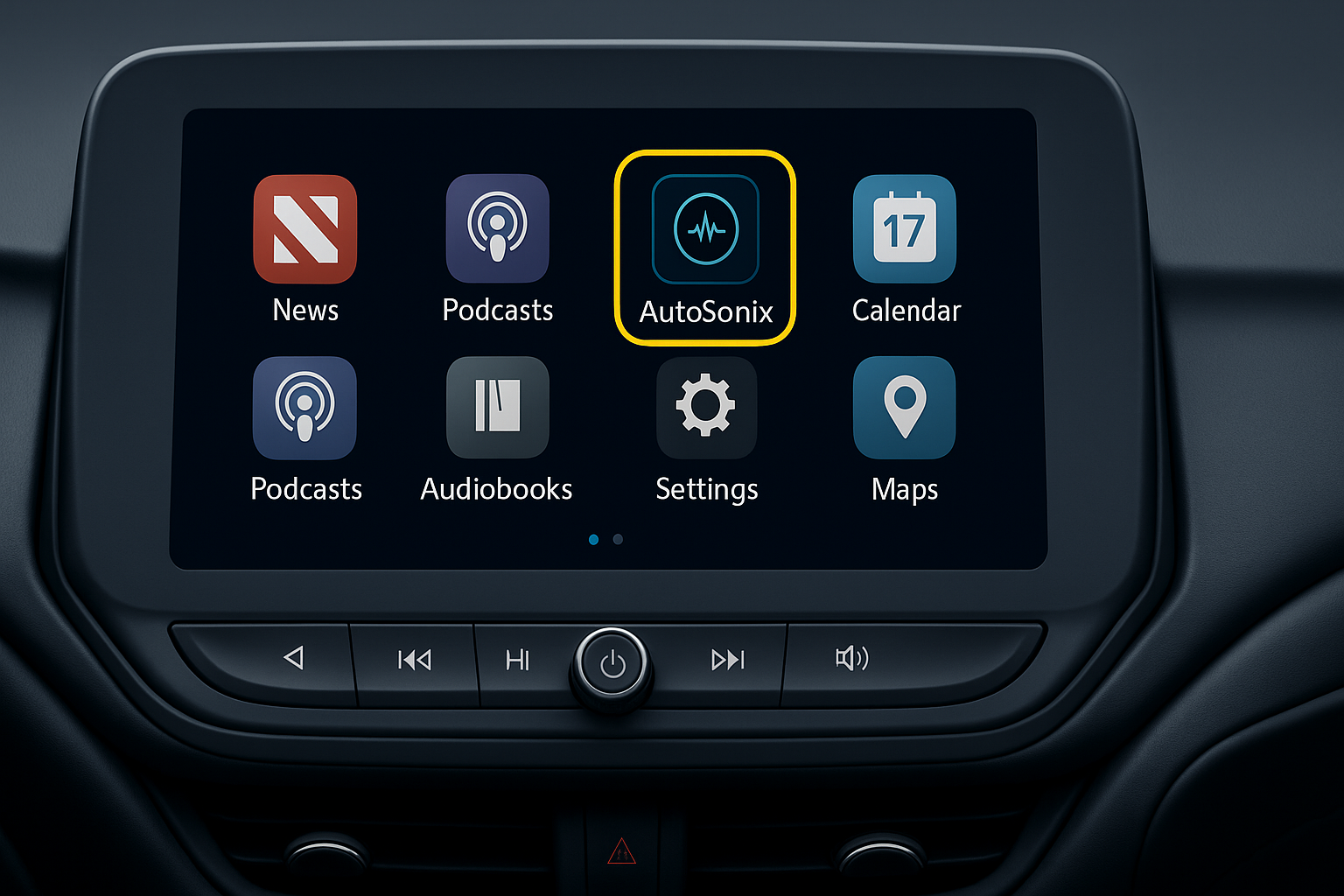
Explore how acoustic insights could reach an infotainment interface and the connected fleet platform.
Phone-level inference is at proof-of-concept stage. The embedded sensor and infotainment graphics illustrate a proposed deployment. Sensor size, power, connectivity, placement and production integration require joint engineering and validation.
THE APPLICATION HORIZON
Develop evidence for acoustic condition monitoring and maintenance review in the selected fleet.
Explore acoustic inputs for recall-prevention initiatives and production quality control.
Investigate additional acoustic profiles for safety and security use cases through dedicated development and validation.
Establish the field baseline.
Develop vehicle history and agreed alert rules.
Engineer vehicle and platform integration.
ENGINEERING REFERENCES / 07
AutoSonix grew from a collaboration between GlobalSense and Condition Now, combining acoustic-AI development with automotive data and inspection experience. These references document the technology and its industry coverage; fleet-specific performance requires separate validation.
Edge Impulse’s case study on GlobalSense automotive sound classification, model iteration and edge-AI development.
Read the case study →01Saeid Safavi’s session on acoustic sensing for fault diagnosis and predictive maintenance, presented at Imagine 2025 at the Computer History Museum.
Watch on YouTube →02The GlobalSense / AutoSonix case study from Elektor’s December 2025–January 2026 Edge Impulse guest edition.
Read the article · PDF →03Coverage of AutoSonix’s acoustic inspection platform and its use in auction and dealership workflows.
Read the article · PDF →04Deployment context: the articles describe edge-first processing options. The current ListenLink inspection workflow captures and uploads recordings for cloud analysis; phone-level inference remains at proof-of-concept stage. Audio handling depends on the deployment architecture.
Context matters. These references show how the technology has been developed and discussed publicly. The TCME fleet PoC is where performance should be tested against agreed service outcomes.
THE NEXT STEP
Complete the mutual NDA, equip TCME’s management team to review the opportunity, then agree a PoC using the capability available today.
Review the proposed PoC